Security testing of the pacemaker ecosystem - Part 1
Introduction, context and methodology Link to heading
This post is the first in a series of five related to the research I have been conducting on the pacemaker ecosystem security during my final year of Master at NTNU. The research was included in an internal project started at SINTEF by Marie Moe back in 2015. This series aims at presenting the results in an easier and less academic way than in the original master’s thesis. I also try to highlight the process and the difficulties I have faced during the project, with the hope that this can be helpful for someone working on a similar project.
This first post lays the foundations for the next ones and gives basic explanations about the BIOTRONIK pacemaker ecosystem we will look at, along with the methodology that was used to approach it.
Coordinated disclosure Link to heading
These research findings were shared with BIOTRONIK in the form of a vulnerability report. BIOTRONIK cooperated according to a Coordinated Vulnerability Disclosure process and appropriately analyzed and validated our report. They then shared their responses to each reported vulnerability, and we discussed each point in detail. During these discussions, BIOTRONIK provided sufficient information to confirm that patient harm arising from the vulnerabilities is very unlikely.
BIOTRONIK recommends that healthcare providers and patients continue to use the investigated devices as intended and follow device labelling.
The CISA advisory is available here.
Timeline of the coordinated disclosure:
- October 2019: Vulnerability report is sent to BIOTRONIK
- November 2019: Discussion between SINTEF and the FDA
- April 2020: BIOTRONIK response is received by SINTEF
- April/May 2020: Discussion between BIOTRONIK, BSI, CISA and SINTEF
- 18th June 2020: CISA’s advisory and disclosure.
The pacemaker ecosystem Link to heading
What is a pacemaker? Link to heading
First and foremost, let’s define what is a pacemaker or an ICD. An Implantable Cardioverter Defibrillator (ICD) is a medical device implanted in the patient’s body to control patient’s heartbeats, usually in case of arrhythmia. ICDs are used for patients with strong arrhythmia, i.e. those whom condition can lead them to faints or even cardiac arrests. The device monitors the patient’s heart rate and sends an electrical pulse when it detects an anomaly.1
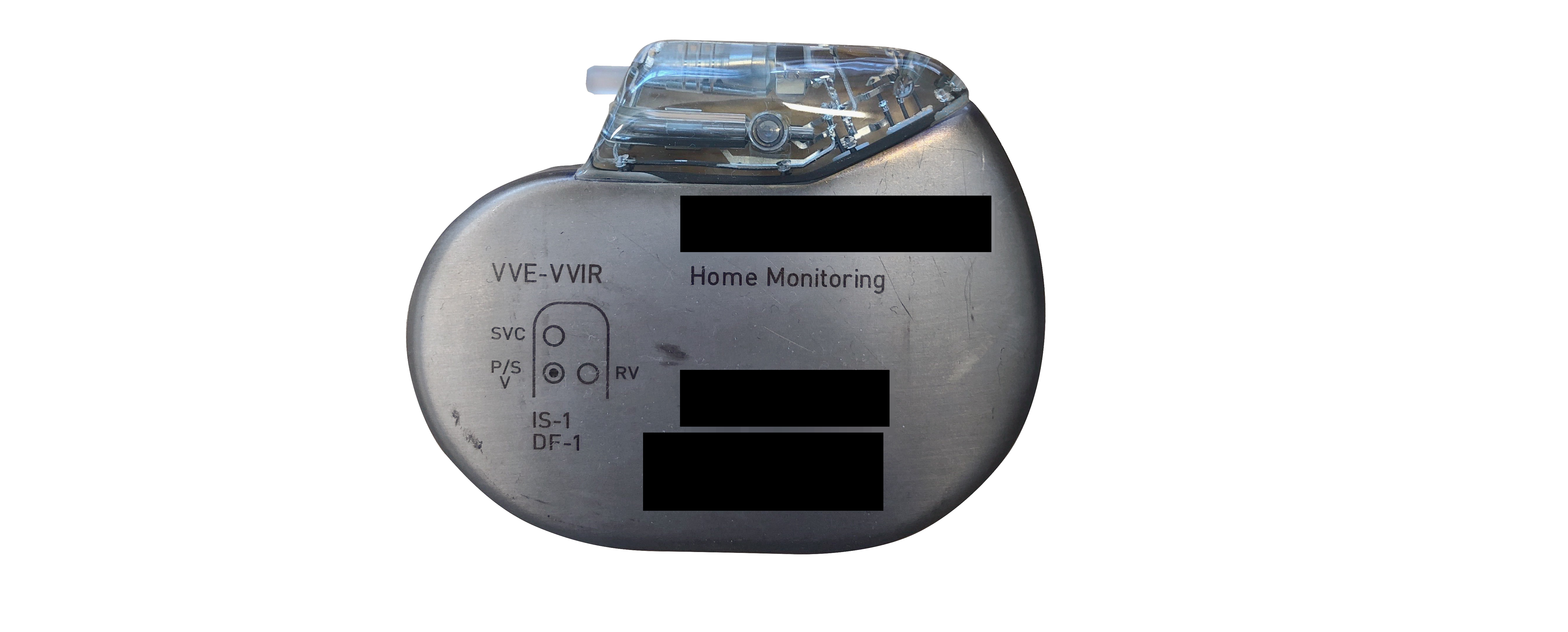
Figure 1: Picture of the pacemaker in SINTEF’s lab
A ICD is presented in Figure 1. The device is of the size of a credit card and has one, two or three wires that are called leads. As explained by the Texas Heart Institute, a pulse generator along with other electronic circuits and a battery are contained inside the implant.1 The difference between a pacemaker and an ICD is that an ICD can deliver shocks, while pacemakers only correct the heart’s rhythm with small electrical stimuli. The shocks delivered by an ICD can be felt by the patient, and he is usually asked by his doctor to report when he got one or more. From now on, we will use only to the term “pacemaker” to refer to both “pacemaker” and “ICD”.
Having to report and then to visit the doctor each time an event occurs can be annoying for patients. That is why pacemaker’s manufacturers have connected the devices wirelessly. That way, a patient can use an external device to gather the data from his pacemaker during the night and automatically send them to a server where a specialized doctor can see them. That allows the doctor to be alerted faster in case of a problem and prevent the patient from unnecessary visits.
The ecosystem Link to heading
As just mentioned, the pacemaker is not a standalone device that is installed inside a patient’s body and left there for years without any interaction with the outside world. It relies on a whole ecosystem to work correctly and efficiently. This ecosystem is composed of multiples devices. Figure 2 shows the ecosystem of the vendor we have been studying, but this is quite generic.
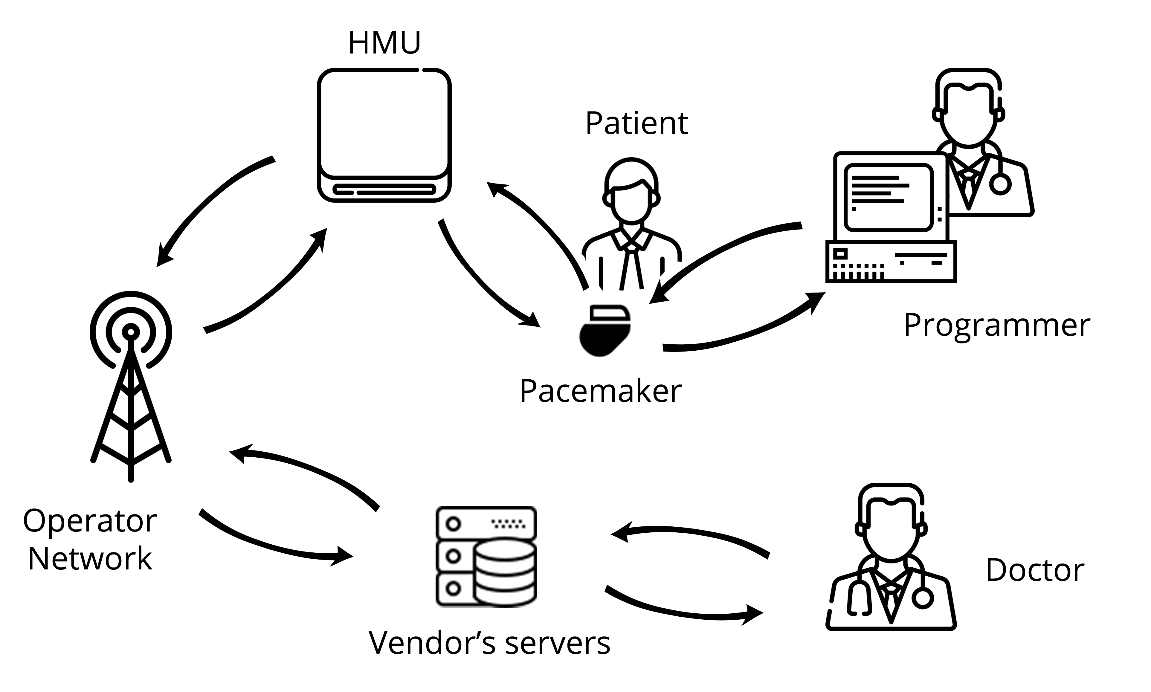
Figure 2: Diagram of the vendor’s pacemaker ecosystem
Here is a description of the different components of the ecosystem:
- The pacemaker: Implanted in the patient’s body, this is the main device of the ecosystem. It generates an electric impulse that helps regulate the heart rate. Programmable pacemakers allow practitioners to select the appropriate pacing for every patient.
- The programmer: The programmer is an external computer used by a practitioner at the hospital to program the pacemaker. This device requires proximity with the pacemaker, which is achieved thanks to the programming head. The communication remains wireless though.
- The Home Monitoring Unit: The HMU is a device aiming at easing the patient’s life by preventing them from visiting their practitioners too often. Indeed, placed in the patient’s home, this device is in charge of downloading the data from the pacemaker and sending to the vendor’s servers for the practitioner to access them remotely.
- The Operator Network: The HMU needs a way to access the internet in order to communicate with the vendor’s servers. Depending on the HMU (see below), the internet can be accessed using a mobile network such as GSM or 3G but also using a regular telephone line.
- Vendor’s Servers: These are the servers the HMU connects to in order to export the patient’s data. This is achieved using the operator network. These servers can be accessed by the practitioner through an online platform.
Scope of the research Link to heading
My project was focused on only one element of the pacemaker ecosystem which is the Home Monitoring Unit. This device, even though it is not mandatory, is interesting in terms of security as it directly interacts with both the pacemaker and the vendor’s server. It also handles the patient’s data. Most importantly, previous researcher have shown that some HMUs can be transformed into a “weapon” and a threat to a patient’s life, by using it to drain the pacemaker’s battery.2 Figure 3 highlights the different scopes that were available to me during my Master’s thesis:
- The interface between the HMU and the vendor’s servers.
- The HMU itself as a standalone embedded device.
- The interface between the HMU and the pacemaker.
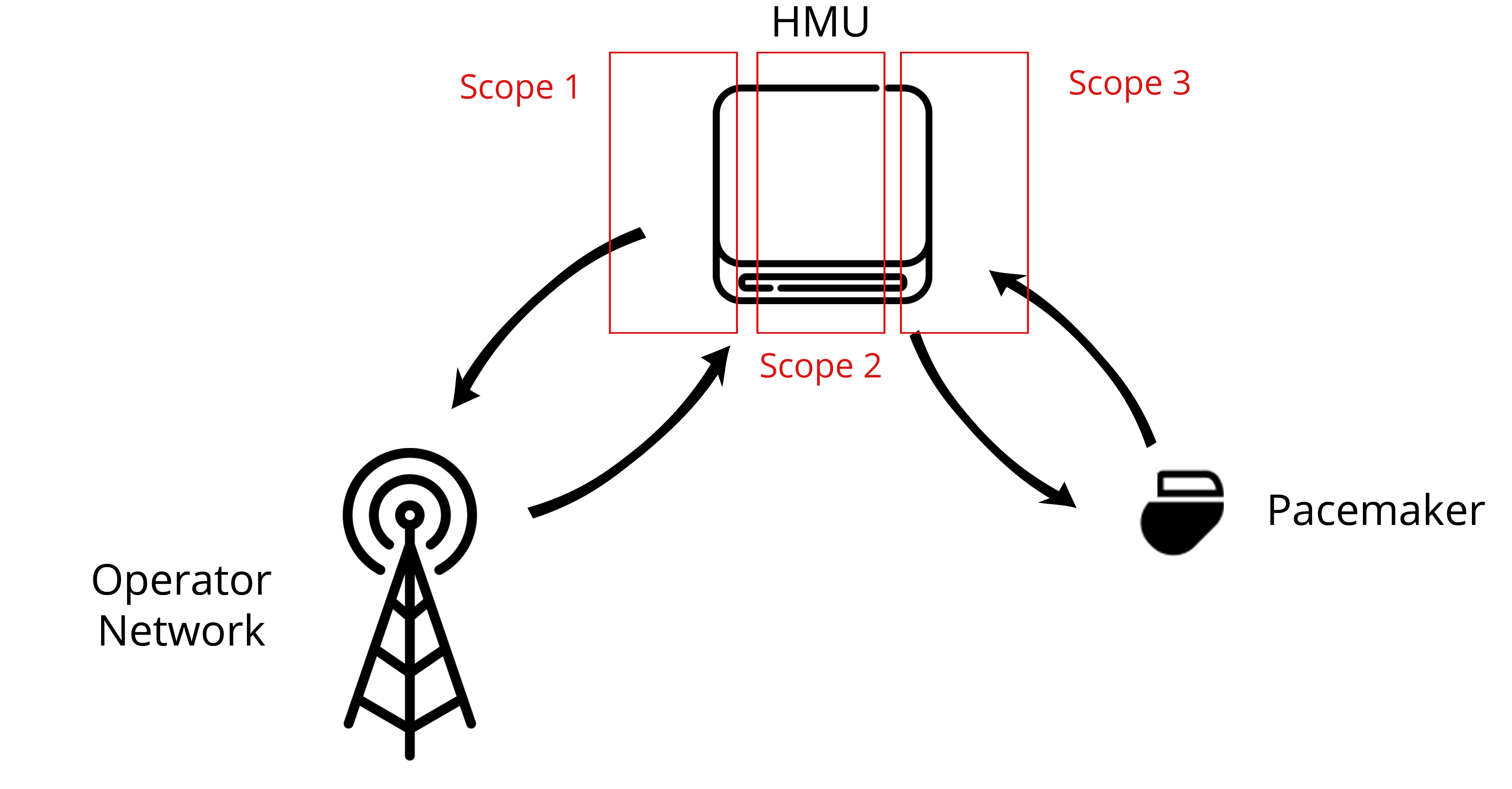
Figure 3: Scopes around the HMU
I ended up focusing on scope 2, with some overlap on scope 1. Scope 3 was left aside mainly because we did not have a working pacemaker available in the lab. Another student from NTNU, Anniken Wium Lie was focusing on scope one, and specifically on the mobile network interface. Even though our scopes are distinct on the paper, many collaborations took place between our projects. Indeed, my findings on the HMU hardware along with the Fake Base Station set up by Anniken allowed us to have more interactions with the device and a better understanding of it.
Black-Box Testing methodology Link to heading
To perform the research, I have been working with the Black-Box Testing Methodology. I won’t go too much into the details of the methodology, but basically it is a way to assess a software, a device or more generally a system from the outside while having very little knowledge about its internals. The attacker is analyzing the outputs of the box obtained by sending some inputs or just by passively listening, and then tries to deduce the internals of the target. Having made some guesses, the attacker can adjust her inputs to confirm her thoughts or to exploit the target (see Figure 4).
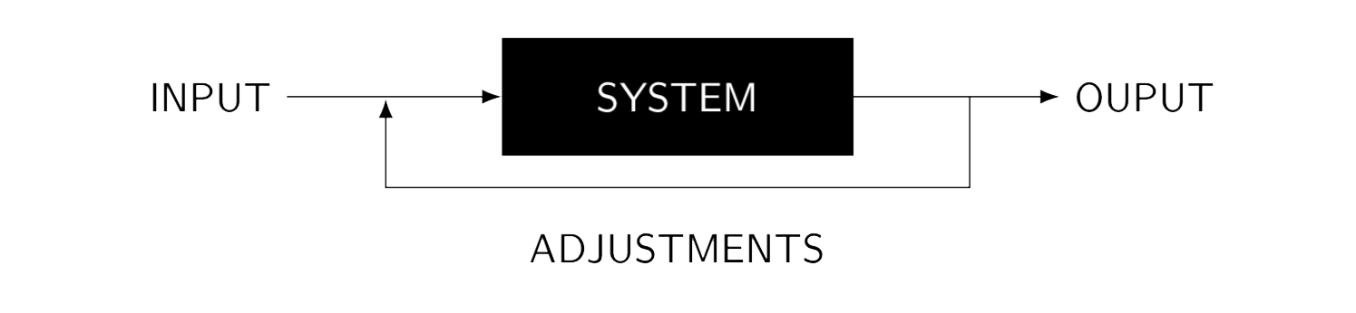
Figure 4: Diagram of the Black Box Testing methodology
This methodology has several advantages compared to others that can be used to assess a system. Indeed, the goal here is to test under real conditions, to fit a real scenario. That means that such a test will include real errors that can be made during the deployment of a system, such as default passwords, misconfigurations in general or even a lack of training of the employees (weak password for instance). It also has a low false-positive ratio as the attackers can assess the risks associated with a vulnerability, i.e. if a given vulnerability is really exploitable or not. A White Box Testing on the other hand, where the attacker has full access to source code and implementation details, might lead to vulnerabilities that are not relevant (not given the goal of a Black Box Security testing at least) because they would never be triggered in a real-world scenario. However, Black Box Testing methodology also has some drawbacks. By definition, the attacker has very little information about the target and might miss some vulnerabilities that would have been detected by code and/or configuration review. It is then clear that a Black Box Testing should not be the only security test performed, even though it is an excellent way to assess a device under real conditions.
My project focused on a proprietary ecosystem, on which I had almost no information apart from the one the vendor is providing the patient with, which is in fact vague and non-technical. Moreover, my goal was to assess the security risks related to that ecosystem in a real-world scenario. Black Box Testing Methodology then fitted well with my constraints and objectives and that is why I decided to use it.
Conclusion Link to heading
This first post was not really technical but aimed to pave the path for the next ones. In the part 2 of this series, we will start the real testing of the device, with the hardware testing.
Go to Part 2 - Hardware Testing of the Home Monitoring Unit.